Terms and definitions
- Shielded metal arc welding (SMAW) -- An arc welding process wherein metals are united by heating with an electric arc between a coated metal electrode and the metal.
- Arc -- The flow of electric current from the tip of the electrode to the base of the metal being welded.
- Electrodes -- Metal rods which conduct a current from the electrode holder to the base metal.
- Base metal -- The metal to be welded or cut.
- Arc length -- The distance from the end of the electrode to the point where the arc makes contact with work surface.
- Crater -- A depression at the termination of a weld.
- Face of weld -- The exposed surface of a weld, made by an arc or gas welding process, on the side from which welding was done.
- Flux -- A fusible material or gas used to dissolve and/ or prevent the formation of oxides, nitrides, or other undesirable inclusions formed in welding.
- Low carbon steel -- Steel containing .20% or less carbon.
- Pass -- A single longitudinal progression of a welding operation along a joint or weld deposit.
- Porosity -- Gas pockets or voids in metal.
- Spatter -- The metal particles given off during welding which do not form a part of the weld.
- Tack weld -- A weld made to hold parts in proper alignment until the final welds are made. (NOTE: This type of welding is for assembly purposes only.)
- Puddle -- That portion of a weld that is molten at the place the heat is supplied.
- Undercut -- A grove melted into the base metal adjacent to the toe of the weld and left unfilled by weld metal.
- Weaving -- A technique of depositing weld metal in which the electrode is oscillated.
- Weld metal -- That portion of a weld which has been melted during welding.
- Whipping -- A term applied to an inward and upward movement of the electrode which is employed in vertical welding to avoid undercut.
- AWS -- American Welding Society
- Deposition Rate -- The amount of filler metal deposited in any welding process; rated in pounds per hour.
II. Types of arc welding machines
A. AC (Alternating current) transformer welder – Current alternating direction 120 times per second
B. AC – DC – Transformer rectifier – Provides either alternating current or direct current
C. Motor generator – Produces DC current
D. Engine generator – Produces DC current
III. Common equipment
A. Welding machine
B. Electrode holder with lead
C. Ground clamp with lead
D. Shield or helmet
E. Gloves
F. Chipping hammer
G. Safety goggles
H. Wire brush
I. Electrodes
J. Pliers
K. Personal protective clothing
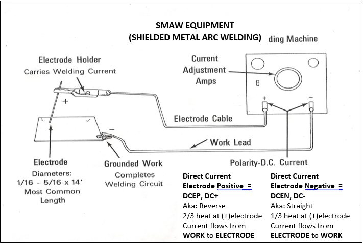
IV. Polarity
A. Reverse (DC+) – Current flows from base metal to electrode
B. Straight (DC-) – Current flows from electrode to base metal
(NOTE: Welding leads must connect to correct terminals if machine has a polarity switch. Otherwise a change in polarity is made by reversing the leads on the terminals.)
V. Factors that determine polarity – Electrode and type of flux on electrode
A. E6010 DC (+) Reverse polarity
B. E6012 AC-DC (-) straight polarity
C. E7018 AC-DC (+) Reverse polarity
D. E7018 AC-DC (+/-) Reverse or straight polarity
VI. Operating machine adjustments
A. Current (amperage) settings
1. Increasing amps – Produces more “heat”
2. Decreasing amps – Produces less “heat”
B. Polarity
VII. Testing for polarity
A. Weld a bead using E6010 DC+ reverse polarity electrode (NOTE: If there is excessive amount of weld spatter and arc is very erratic, machine is set on straight polarity (electrode lead negative, work lead (ground) positive. Reverse polarity should have electrode positive, work lead (ground) negative. The same practice would apply if machine is set on AC)
B. Strike arc with carbon electrode (NOTE: If arc is smooth and quite, it is set on straight polarity. If carbon becomes extremely hot and pieces break off and black smudges appear on work piece, it is set on reverse polarity.)
VIII. Types of Electrodes
A. Mild steel
B. Low hydrogen-low alloy
C. Non-ferrous
D. Hard surfacing
E. Cast iron
F. Stainless steel
A. Welding machine
B. Electrode holder with lead
C. Ground clamp with lead
D. Shield or helmet
E. Gloves
F. Chipping hammer
G. Safety goggles
H. Wire brush
I. Electrodes
J. Pliers
K. Personal protective clothing
IV. Polarity
A. Reverse (DC+) – Current flows from base metal to electrode
B. Straight (DC-) – Current flows from electrode to base metal
(NOTE: Welding leads must connect to correct terminals if machine has a polarity switch. Otherwise a change in polarity is made by reversing the leads on the terminals.)
V. Factors that determine polarity – Electrode and type of flux on electrode
A. E6010 DC (+) Reverse polarity
B. E6012 AC-DC (-) straight polarity
C. E7018 AC-DC (+) Reverse polarity
D. E7018 AC-DC (+/-) Reverse or straight polarity
VI. Operating machine adjustments
A. Current (amperage) settings
1. Increasing amps – Produces more “heat”
2. Decreasing amps – Produces less “heat”
B. Polarity
VII. Testing for polarity
A. Weld a bead using E6010 DC+ reverse polarity electrode (NOTE: If there is excessive amount of weld spatter and arc is very erratic, machine is set on straight polarity (electrode lead negative, work lead (ground) positive. Reverse polarity should have electrode positive, work lead (ground) negative. The same practice would apply if machine is set on AC)
B. Strike arc with carbon electrode (NOTE: If arc is smooth and quite, it is set on straight polarity. If carbon becomes extremely hot and pieces break off and black smudges appear on work piece, it is set on reverse polarity.)
VIII. Types of Electrodes
A. Mild steel
B. Low hydrogen-low alloy
C. Non-ferrous
D. Hard surfacing
E. Cast iron
F. Stainless steel
IX. Common electrode sizes
A. Range in size from 1/16” to 5/16”
B. Common sizes 3/32”, 1/8”, 5/32”, 3/16”, 7/32”, ¼”, 5/16”
X. Determining electrode size – Determined by diameter of bare end of electrode
XI. Purpose of flux coating
A. Stabilizes arc
B. Shields molten puddle from air
C. Floats impurities out of puddle
D. Forms slag and slows cooling
E. Provides deoxidizers and scavengers to prevent porosity of weld zone
F. Provides alloying elements for higher strength welds
G. Provides iron powder to increase the disposition rate
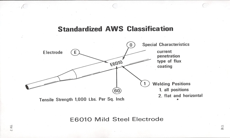
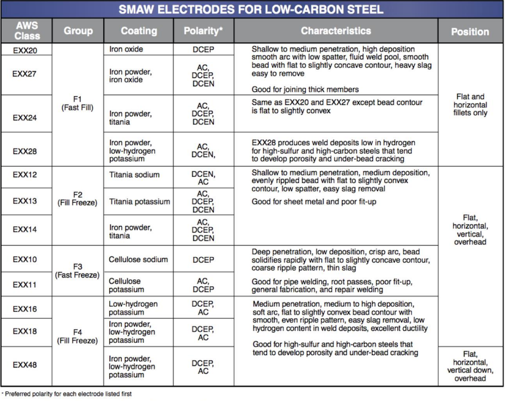
XIII. AWS electrode classification (attached)
A. E – Stands for electrode
B. First two digits – Indicate tensile strength deposited in a thousand pounds per square inch
C. Third number – Indicates welding Position
D. All positions
E. Flat and horizontal
F. Fourth digits – Represents special characteristics and usability of the rod
G. Current
H. Penetration
I. Type of flux coating
XIII. Factors for selecting electrodes
A. Base metal strength properties
B. Base metal composition
C. Welding position
D. Welding Current
E. Joint design and fit-up
F. Thickness and shape of base metal
G. Service conditions and/or specification
H. Production efficiency and job conditions
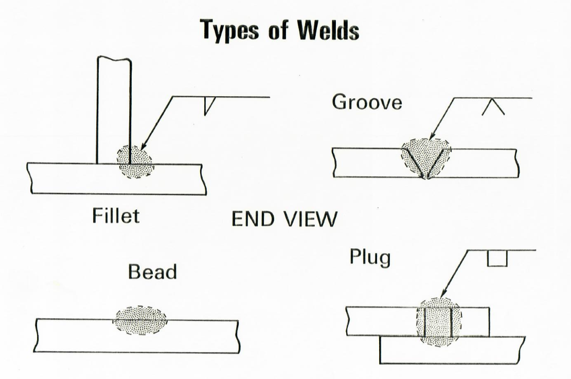
XIV. Types of welds (Transparency 3)
A. Bead
B. Fillet
C. Groove
D. Plug
A. Bead
B. Fillet
C. Groove
D. Plug
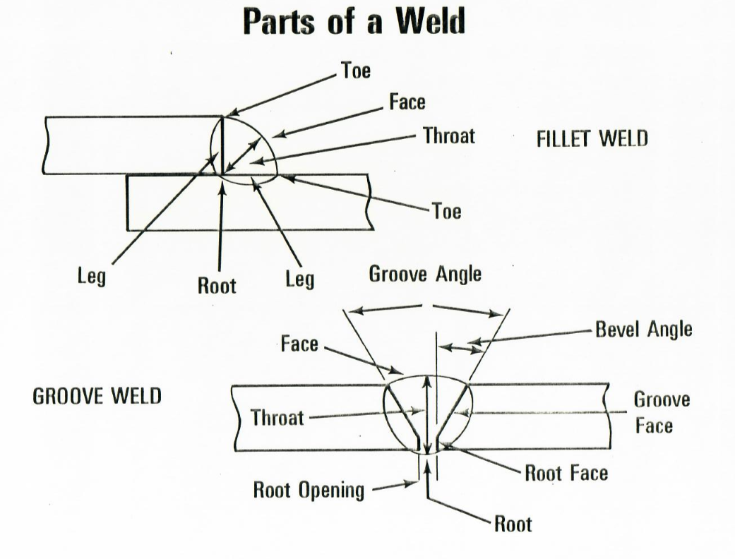
XV. Parts of groove and fillet welds (Transparency 4)
A. Groove weld
1. Face
2. Root
3. Root face
4. Root opening
5. Groove face
6. Groove angle
7. Bevel angle
8. Throat
B. Fillet weld
1. Toe
2. Face
3. Throat
4. Leg
5. Root
A. Groove weld
1. Face
2. Root
3. Root face
4. Root opening
5. Groove face
6. Groove angle
7. Bevel angle
8. Throat
B. Fillet weld
1. Toe
2. Face
3. Throat
4. Leg
5. Root
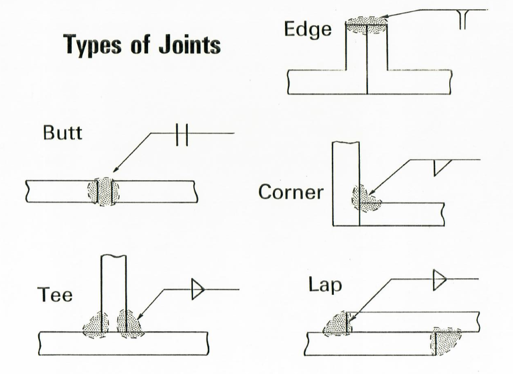
XVI. Types of weld joints (Transparency 5)
A. Butt
B. Corner
C. Tee
D. Lap
E. Edge
XVII. Reasons for poor welds
A. Improper machine adjustment
B. Improper electrode and size
C. Improper movement of electrode
D. Improper angle of electrode
E. Improper base metal preparation
F. Improper arc length
A. Butt
B. Corner
C. Tee
D. Lap
E. Edge
XVII. Reasons for poor welds
A. Improper machine adjustment
B. Improper electrode and size
C. Improper movement of electrode
D. Improper angle of electrode
E. Improper base metal preparation
F. Improper arc length
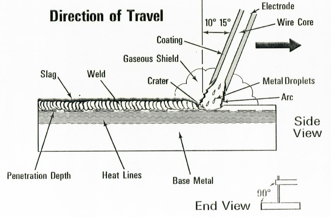
XVIII. Parts of welding process (Transparency 6)
A. Slag
B. Weld
C. Electrode
D. Wire core
E. Coating
F. Arc
G. Crater
H. Penetration
I. Base metal
J. Heat lines
K. Gaseous shield
L. 10 – 15 degrees
XIX. Methods of striking arc
A. Tapping
B. Scratching
XX. Safety precautions
A. Keep equipment in good, clean, dry condition
B. Make sure all electrical connections are tight, clean, and dry
C. Use correct size welding cable—do not overload
D. Be sure cables, holder, and connections are properly insulated
E. Cut off power to welder before cleaning machine or making internal adjustments
F. Never change polarity or current settings while machine is under load
G. Observe normal operating care for electrical hazards
H. Keep work area neat, clean and dry
I. Remove flammable materials from welding area or shield them
J. Do not weld near volatile, flammable liquids or gases
K. Do not weld or cut on containers such as drums, barrels, or tanks until you know there is no danger of fire or explosion
L. Dispose of hot electrode stubs in a metal container
M. Never strike an arc on a compressed gas cylinder
N. Protect your eyes from rays of the arc; wear a head-shield with the proper filter plates when welding or cutting
O. Wear protective chipping goggles when chipping off weld slag (NOTE: Chip away from your face.)
P. Wear leather gloves and protective clothing such as an apron, sleeves, etc. to shield against the arc rays and sparks; button up shirt collar
Q. Use a non-reflecting welding curtain to protect others in the area from the arc rays
R. Be sure work area has adequate ventilation-plenty of fresh air; special precautions are necessary when welding lead, zinc, beryllium copper, or cadmium
S. Do not pick up hot metal
T. Always open main switch or disconnect plug when checking over a welder
U. Do not leave electrode holder on welding table or in contact with grounded metal surface
V. Keep tools and metal in their proper locations
| SMAW Quick Guide |
