Terms and definitions
A. Blueprint — A written message conveyed from the draftsman to the workman containing technical information.
B. Dimensions — A process of illustrating the size of various objects.
C. Views — A drawing illustrating the part of an object one could see if standing directly in front.
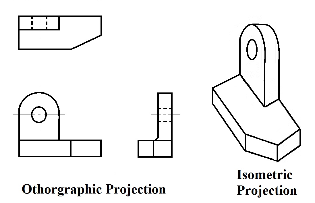
D. Orthographic projection — A method of illustrating several views of an object.
E. Pictorial view — An illustration showing three or more sides of an object.
F. Size dimension — A type of dimension that tells how large or small an object is.
G. Location dimension — A type of dimension that locates a feature on an object.
H. Size description — The notes and dimensions that tell the size of an object.
I. Shape description — The views that illustrate the shape of an object.
A. Blueprint — A written message conveyed from the draftsman to the workman containing technical information.
B. Dimensions — A process of illustrating the size of various objects.
C. Views — A drawing illustrating the part of an object one could see if standing directly in front.
D. Orthographic projection — A method of illustrating several views of an object.
E. Pictorial view — An illustration showing three or more sides of an object.
F. Size dimension — A type of dimension that tells how large or small an object is.
G. Location dimension — A type of dimension that locates a feature on an object.
H. Size description — The notes and dimensions that tell the size of an object.
I. Shape description — The views that illustrate the shape of an object.
|
Welding Joint Types
A weld joint is the term used to describe the location where two or more pieces of metal join together. In order to obtain a sound weld, and to ensure the most economical use of filler metal, the joint design must be considered in any type of weldment. This will depend upon several factors including:
|
|
|
Welding Symbols
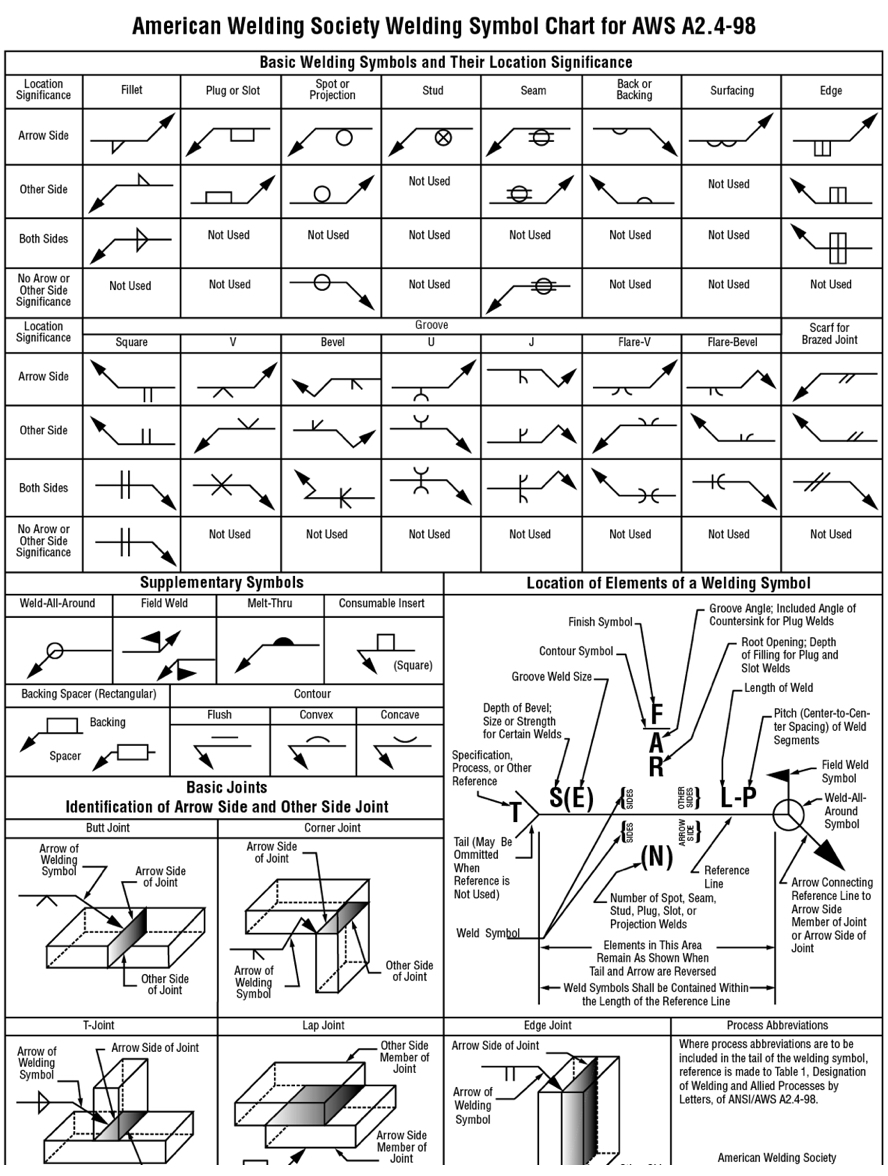
Welding symbols are defined by the American Welding Society in ANSI/AWS A2.4 Standard Symbols for Welding, Brazing, and Nondestructive Examination. This standard should be referenced for all engineering documentation to ensure quality and consistency in manufacturing of welded structures. Many companies use welding symbols incorrectly and do not refer to this standard. This causes confusion and can lead to significant quality problems. Because welding symbols have an element of interpretation the AWS Standard is very thorough and complete in helping identify the intended weld that the symbols implies. This section is intended to stress the importance of using the AWS standard when using welding symbols. The welding symbols chart, Figure 62, helps identify welding symbols. An excellent resource to learn welding symbols can be purchased from The Hobart Institute of Welding Technology: Symbols for Welding. This programmed self-paced course provides a simple yet complete method for students to learn and understand welding symbols. |
|
Reading prints
Originally, prints were referred to as blueprints because the process used to make them. A Print, or a set of plans is the necessary information to complete a job. These drawings are tools, and if a picture is worth a thousand words, than a Working drawing must be worth millions! Just think how many words would it take to tell someone how to build an off road truck, a bridge, or something as simple as a shelf?
Originally, prints were referred to as blueprints because the process used to make them. A Print, or a set of plans is the necessary information to complete a job. These drawings are tools, and if a picture is worth a thousand words, than a Working drawing must be worth millions! Just think how many words would it take to tell someone how to build an off road truck, a bridge, or something as simple as a shelf?
Information found on a blueprint
A. Description
B. Date
C. Object
D. Company
E. Scale
F. Last change
G. Size of object
H. Example
A. Description
B. Date
C. Object
D. Company
E. Scale
F. Last change
G. Size of object
H. Example
|
Assignment: Describe your Lego.
10 Points possible. |
| ||
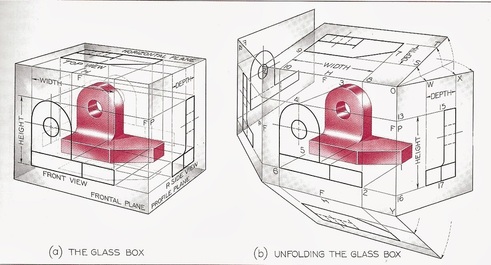
Pictorial sketches or drawings look like a "Picture" because they convey a sense of perspective and realism of the object being viewed. Drawings should contain enough information to aid the welder to produce the weldment. The Glass box shows an object inside with Orthographic projections (multiview), each of the multiview drawings are shown two-dimensionally. They show all details that are necessary to understand the basic shape and locations of other components.
|
|
Major views of a pictorial drawing: Front, Top, Side (right)
Basic elements of a blueprint
A. Lines — Give shape and dimension to the object
B. Dimensions — Give size and location of various segments of items being constructed
C. Notes — Give details of construction not shown by lines
Dimensions to look for on a blueprint
A. Height
B. Width
C. Depth
A. Lines — Give shape and dimension to the object
B. Dimensions — Give size and location of various segments of items being constructed
C. Notes — Give details of construction not shown by lines
Dimensions to look for on a blueprint
A. Height
B. Width
C. Depth
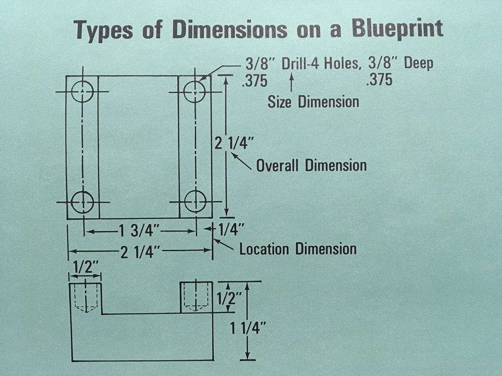
Types of dimensions: (Above)
A. Overall — Describes a total distance such as the complete length, width, or thickness of a part.
B. Size — Gives information concerning the size of a part.
C. Location — Gives information concerning the location of some detail of construction such as a hole.
A. Overall — Describes a total distance such as the complete length, width, or thickness of a part.
B. Size — Gives information concerning the size of a part.
C. Location — Gives information concerning the location of some detail of construction such as a hole.
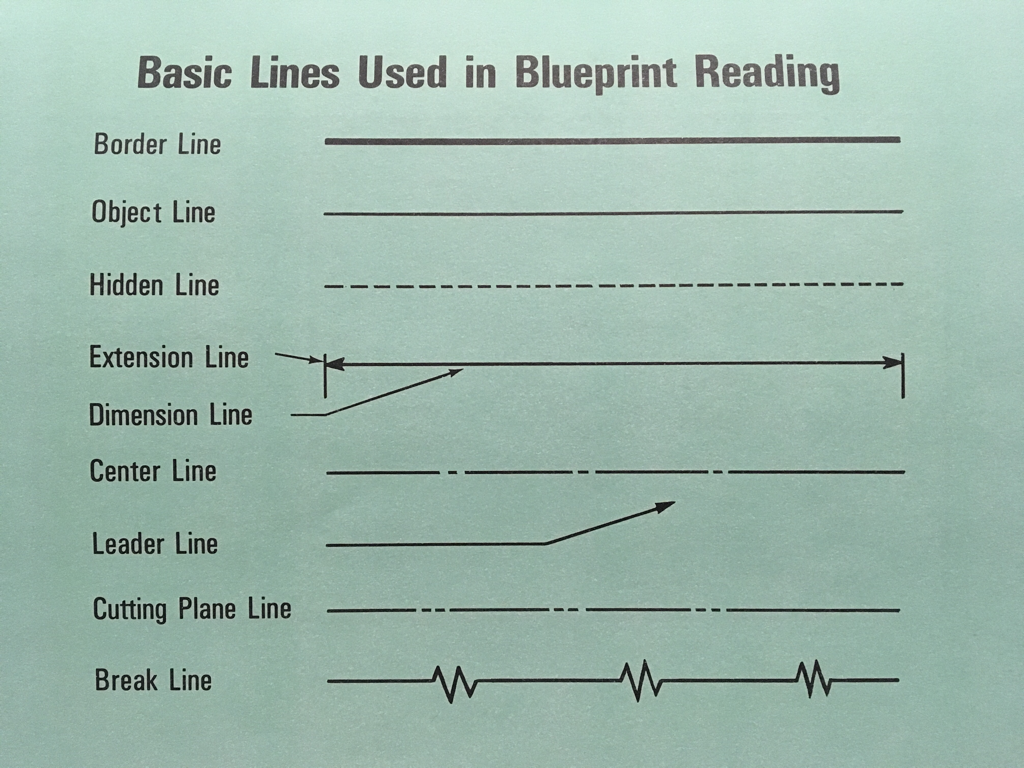
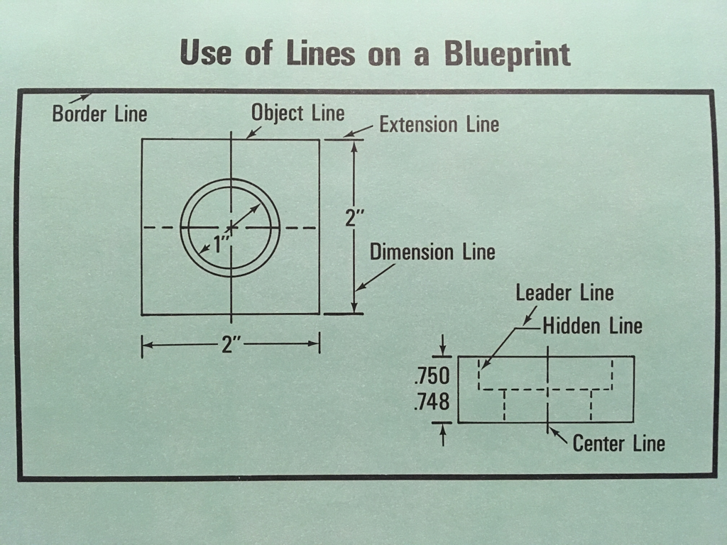
Lines used in blueprint reading: (Above)
A. Border — Serves as a frame for the blueprint
B. Object — Indicates the outline of an object
C. Hidden — Represents an edge that cannot be seen from the outside of the object
D. Extension — Indicates the exact distance the dimension describes
E. Dimension — Extends between the extension lines to clarify dimensions
F. Center — Used to locate the center of a circle or a curved surface
G. Pointer — Shows the detail described by a dimension or note
H. Cutting plane — Used to show the shape of complicated parts
I. Break — Used to show interior detail
Resources: Assignments:
|
| ||||||||
| Welding Symbols Presentation |
